UP-500 – the Connection System for Effective HV Bushing Condition Assessment

The «UP-500» connection system is used for periodic monitoring of high voltage (HV) bushing insulation condition of transformers and other HV equipment. These can be both the oil-filled and dry bushings. «UP-500» system could be installed on a bushing test tap with the operating voltage of 110 ÷ 750 kV.
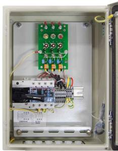
With «UP-500» system installed on the HV equipment, it is possible to measure the bushing parameters on-line by a portable device any time. To do this, open the «UP-500» protective enclosure and connect the diagnostic device to the slots of the printed-circuit board (PCB). After that, shut off the sensor circuits from «the ground» by turning a special breaker. Thus, the diagnostic device appears to be directly connected to the test tap monitored bushing.
In the same way any portable devices for bushing insulation dissipation factor measurement or C1 capacity measurement can be connected to «UP-500» system. A portable partial discharge (PD) measuring device can also be connected to the same slots for HV pulse measuring. Thus, the bushing insulation condition can be assessed and the insulation defect specified on-line.
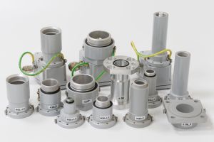
The basic part of «UP-500» connection system are the multipurpose «DB-2» sensors for leakage current and PD measurement, produced by DIMRUS. The sensors of this type are used for a long time; they are rather reliable. DIMRUS produces more than 10 design types of «DB-2» sensors. This is due to the fact that different manufacturers of high-voltage bushings use their unique design of the bushing test tap.
There are three test tap protection levels in «UP-500» system, both inside the sensors and in the PCB

- The test tap protection against lightning surges and switching surges inside «DB-2» sensors. This protection is for maximal pulse currents of 10kA; it is dual redundant.
- The protection against the break of the cable which connects the sensor to the PCB. This option limits the maximal voltage on the bushing test tap at no more than 150V, if the cable breaks. The protection is inside the «DB-2» sensor, it is also dual redundant.
- The additional test tap protection for the modes when the bushing parameters are not measured. In these modes the test tap is manually grounded by turning the breaker with a visible contact, which is set on the DIN-rail inside the enclosure.
All in all, the three supplementary options provide maximal test tap protection from damage and insure the staff safety during the bushing parameter measurement.
The «UP-500» system standard supply set includes
- Three complex «DB-2» sensor of a certain type, settled beforehand, for the definite type of a test tap.
- The PCB in the protective enclosure.
- The set of coaxial cables in stainless steel hose for the sensors connection to the plate - 45 meters (15 meters for each sensor).
When ordering «UP-500» system, it is necessary to give all he information about the bushings at which the sensors are planned to be installed (the manufacturer, the test tap design, etc.).
Optionally, two or more PCB can be installed into one enclosure. Thanks to that, it is possible to measure the parameters of HV and MV of one transformer by connecting the measuring devices to different PCB, or carry out the measurements at different bushing phase combinations.
The «UP-500» System Specifications
| The number of bushings | 3 |
| Rated voltage, kV | 110 ÷ 750 |
| Leakage current range, A | 0,005 ÷ 0,200 |
| Operation temperature range, °C | -60 ÷ +80 |
| Protective enclosure dimensions, mm | 300х430х150 |


