


TDM-M – The Diagnostic Monitoring System for Power Transformers of 110 ÷ 330 kV
The «TDM-M» (Transformer Insulation Monitor) monitoring system is for transformers with operating voltage of 110 ? 330 rV. This class of transformers is the most wide-spread in power transmitting infrastructure. At the same time there is very narrow spectrum of the on-line diagnostic and monitoring means for the transformers of this class.
The «TDM-M» system combines complex approach and high efficiency of power transformer defect diagnostics. It is a complete and rather inexpensive hardware-software system, which has no analogs in the market.
The «TDM-M» system monitors the following parameters:
- The condition of the transformer insulation winding - it is diagnosed by high-voltage partial discharge (PD) measurement and analysis. There is the PD-Expert software which allows specifying the type of the defect and the level of its development.
- The transformer bushing (OIP and RIP) condition by leakage current measurement, bushing capacity C1 calculation and dissipation factor calculation. Such calculations are done for absolute and relative dissipation factors, in dependence of the primary sensors' arrangement. The additional factor for bushing insulation condition monitoring is the measurement and analysis of the PD in bushings.
- The vibration condition of the transformer by analyzing the signal of the three sensors mounted on the transformer tank surface. The level and the spectrum of the vibration signal allow assessing the transformer condition in the whole and the condition of the transformer structural elements.
- The efficiency of the transformer cooling system by using the simplified adaptive heat model of the power transformer.
- The condition of the transformer OLTC in case the additional «LTC-Monitor» intellectual sensor is used with the «TDM-M» system, connected to it by RS-485 interface.
The «TDM-M» measuring device can operate in wide temperature range, that is why the device is usually mounted near the monitored transformer or on the transformer tank itself. Such a way of the device mounting allows to use shorter primary sensors' connection cables and so to raise the system sensitivity and to decrease the noise influence.
The «TDM-M» System Features
The measurement device of the «TDM-M» system is a complete and self-sufficient device with all the transformer equipment monitoring functions.
The device provides:
- Data collection from primary sensors in the periods when the data is the most informative and reliable.
- Checking of the measured parameters for possible surpassing of the warning/alarm thresholds.
- The use of the measured data in the in-built mathematic models, which carry out the transformer defect condition diagnostics.
- The analysis of the transformer condition trends; forecasting transformer parameters' change in quantity and quality with time by use of the adaptive mathematic models.
- Informing the staff about the current defect conditions by inbuilt relays and the information channels for SCADA connection. Such information is considerably benefits from adding the results of trend analysis and the defect development forecasts.
The inbuilt archiving means and the considerable memory capacity for data storage allows the «TDM-M» system to operate in on-line mode for rather a long time – up to one year – without connection to SCADA.
The «TDM-M» system is supplied with «SKI», or «iNVA» specialized software for use with PC. The software gets the data from the device, displays it, and gives the opportunity for additional transformer condition analysis.
The «SKI» software is for local monitoring arrangement. The more resent «iNVA» software is for complex monitoring system creation; it allows integrating the data into the «Smart Grid» system through the IEC 61850 protocol.
For the «TDM-M» to operate efficiently it is necessary to mount up to 16 sensors on the transformer:
- «DB-2» universal sensors (leakage current and PD measuring) – 3 pieces; the sensors are mounted on the transformer bushings' test taps. Thanks to the use of the double protection in the sensors the bushing is well-protected even if the sensor cable breaks down. By the sensors the bushings' leakage current and the PD in the transformer winding insulation and bushings are measured.
- «IFCT-5» sensors – 3 pieces (load current measuring); the sensors are mounted on the conductors of the measuring transformers HV windings. The data on the load current of the transformer primary winding is used in the mathematic diagnostic models of the «TDM-M» system.
- Two sensors in the neutral circuit of the transformer primary winding for zero string power frequency measurement and HV PD currents measurement in the neutral.
- Vibration sensors – 3 pieces; the sensors are mounted on the transformer tank surface. The sensors monitor the fastening of the basic transformer elements.
- Temperature sensors – 2 pieces; the sensors are mounted on the top and bottom of the transformer tank. The temperature data from the sensors is used in the transformer cooling system mathematic model.
- The ambient temperature and humidity sensors. The data from the sensors raises the efficiency of the inbuilt mathematic models.
- «LTC-Monitor» sensor for OLTC condition monitoring (option). The sensor monitors OLTC running under different conditions, and helps to analyze the electro mechanic processes during the device switching on.
- The sensor of dissolved gases in oil monitoring (not by DIMRUS); (option). The use of such data together with the PD analysis in the transformer tank considerably raises the reliability of the defect diagnostic algorithms.
In dependence of the task set before the definite monitoring system, less sensors could be used.
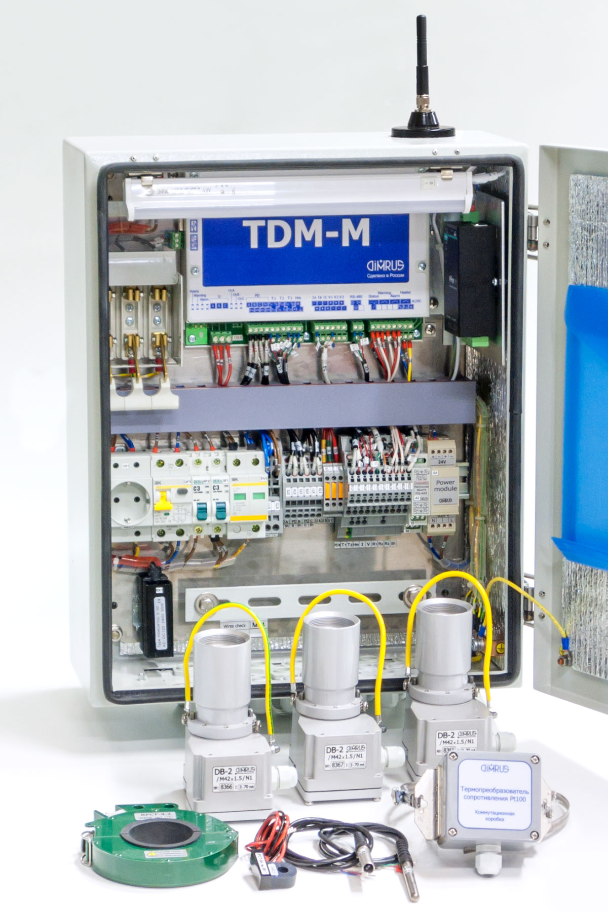
The «TDM-M» System Design
The measuring device of the «TDM-M» system is a complete module of 240*180*50 mm. The cables could be connected to the device itself, but the optimal variant is they connection to the mounting case with terminal blocks.
The measuring device, as well as all the sensors, operate in the standard industrial temperature mode. If the system is planned for the use in the lower ambient temperatures (up to -60° C) then the additional heater should be used. The device constantly measures the temperature inside the mounting case, and can control the heater operation with the inbuilt relay.
The «TDM-M» Monitoring System Specifications
| Rated voltage HV of the monitored transformer, kV | 110 and more |
| The number of the monitored bushings | 3 |
| HV leakage current range, mA | 5 ÷ 30 |
| The number of PD measurement cannels | 4 |
| PD frequency range, MHz | 0,5 ÷ 15,0 |
| SCADA connection interface through RS-485 | Twisted-pair cable |
| PC connection port | USB |
| Operational temperature range, °C | -40 ÷ +60 |
| Power supply, V | AC/DC 120 ÷ 260 |
| Consumer power, W | 50 |
| Mounting case dimensions, mm | 400*500*200 |