


Monitoring Systems for Oil-Filled Power Transformers of up to 35 kV
The TDM-10 Monitoring System for Oil-Filled Transformers of up to 15 kV
The TDM-10 monitoring system is for operational monitoring and diagnostics of oil-filled power transformers with an operating voltage of up to 15 kV. It monitors the transformer condition, and helps to estimate its residual life.
The TDM-10 monitors 6 main parameters of the power transformer:
- Oil temperature in the transformer tank – helps to determine the transformer load capacity and to calculate the insulation remaining life.
- Moisture content in the tank oil – determines the oil’s dielectric strength and its ability to operate at low temperatures.
- The oil level in the tank - a parameter of operational protection.
- Discharge activity inside the tank – the sign of the transformer insulation defects.
- Vibration in the transformer tank – characterizes the condition of transformer mechanical structure.
- Pressure inside the transformer tank.
The primary and final information about the transformer condition passes from the TDM-10 system into SCADA, which monitors all the high-voltage electrical equipment and manages the repair and maintenance services of the substation. The TDM-10 system supports three communication interfaces:
- Wired isolated RS-485 communication interface. Using this interface, you can transfer information into SCADA, configure the TDM- 10 operating modes, and conduct specialized one-time measurements of the transformer operation parameters. The interface is used to create an integrated control system for high-voltage substation equipment.
- Bluetooth wireless communication interface for data communicating to the smartphone, tablet, laptop, to control the operating modes of the TDM-10 system. Bluetooth range is tens of meters. This interface is usually used for stand-alone monitoring systems, when the information about the transformer condition is periodically read from the device to the smartphone with special software installed, during periodic walk-arounds of the equipment by the operating personnel.
- LoRa wireless communication interface (LoRaWan). The LoRa range is as long as several kilometers. The second advantage of the LoRa interface is the use of double encryption of information in it. The most significant drawback of the LoRa interface is its low bandwidth: one packet of information contains only a few tens of bytes. Usually this can only be integral information about the monitored transformer condition.
The TDM-10 device minimal configuration supports Bluetooth wireless interface. If necessary, the device can be equipped with hardware for additional interfaces: wired RS-485 and wireless LoRa.
When ordering a TDM-10 system, the user needs to decide in advance on the set of additional communication interfaces necessary. The wired RS-485 interface and in addition the wireless LoRa interface can be installed in the TDM-10 device. In this case, the Bluetooth interface will be available only when the lid of the device is open (or only at a very close distance, several meters), since the metal case of the device provides space for the antenna of only one wireless interface.
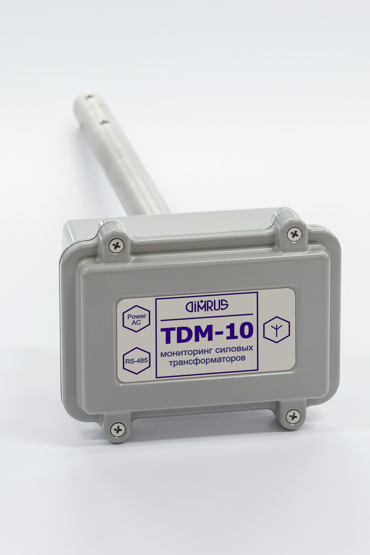
The TDM-10 monitoring system device consists of two parts as shown in the figure: the square sealed metal case and the cylindrical part. The square upper part houses the electronics. From below, the power cable and the wired RS-485 communication interface cable enter it. The third (plastic) cable gland houses the antenna of the user-selected wireless interface.
In the lower cylindrical part made of the stainless steel the sensors are located. The cylindrical part is inserted into the transformer tank; its length depends on the transformer tank cover construction.
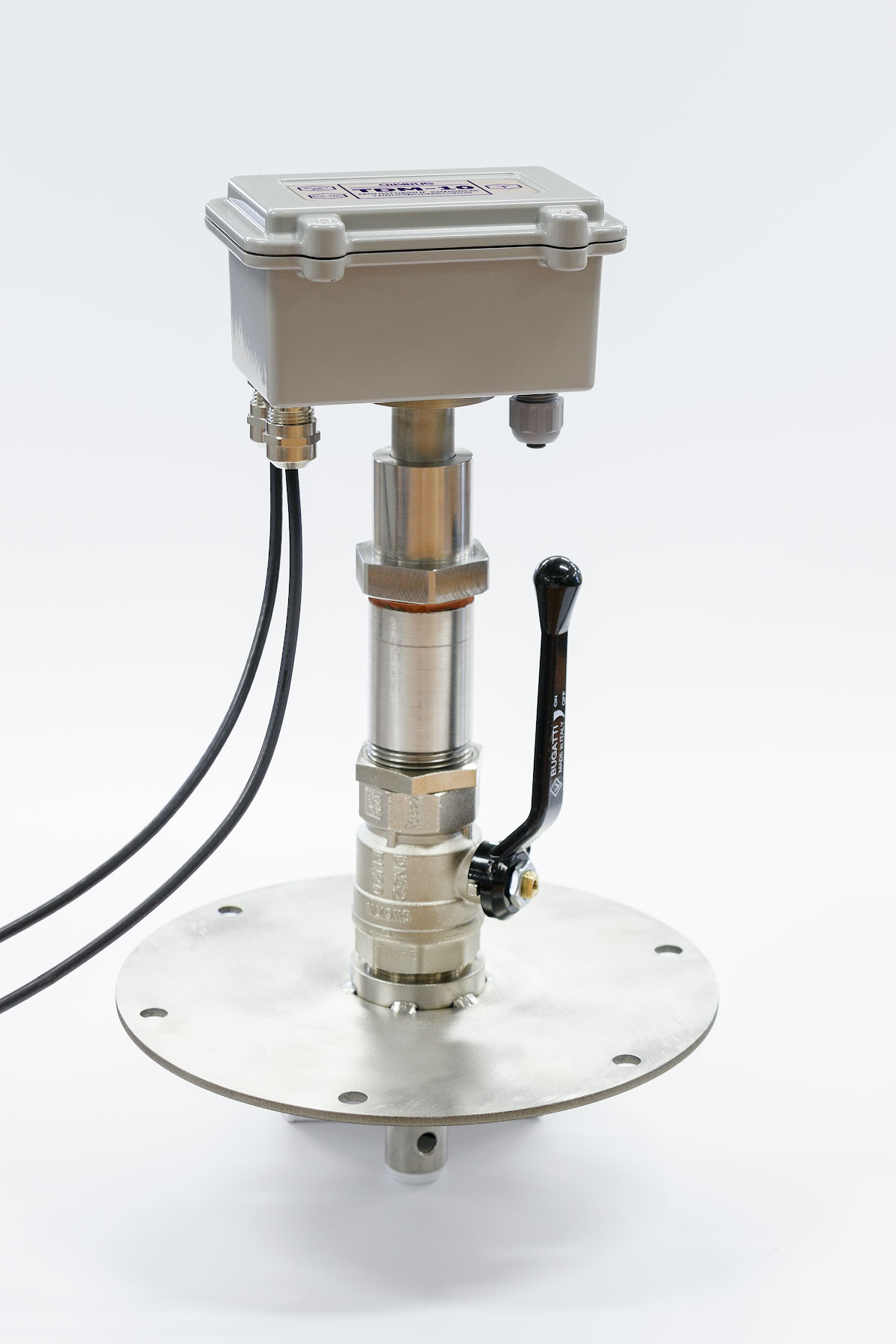
The TDM-10 device is mounted directly on the top cover of the transformer tank. For these purposes, either a regular oil filler neck can be used, or a special adapter flange with a sealing unit. The design of the adapter depends on the design of the transformer cover, an example of the design is shown in Figure 2.
The installation of the adapter flange on the top cover of the transformer tank is usually done on the disconnected transformer without draining the oil. Any installation and dismantling of the TDM-10 measuring device in the adapter flange is carried out quickly and without draining the oil due to the use of a ball valve and the sealing unit in the upper part of the mounting node.
After mounting the TDM-10 device, the connection and activation of the TDM-10 monitoring system is done out simply and quickly. Since all the sensors of the monitoring system are located in the cylindrical part of the device case, immersed into the transformer tank oil and are already connected to the measuring circuit, it is necessary to power the device only. To do this, you need to connect two wires to the terminals of the secondary winding of the transformer: to the phase and neutral point of the secondary winding. In this case, the monitoring system will be turned on and off automatically when the monitored transformer is turned on and off.
If the TDM-10 system is supposed to operate in stand-alone mode using only wireless communication interfaces, then only the power cable needs to be connected. If the TDM-10 is to be connected to SCADA via a wired RS-485 interface, then it is necessary to connect an information cable.
The advantages of using the TDM-10 monitoring system are:
- The TDM-10 system is the most effective and relatively cheap solution for 6-10 kV power distribution transformers monitoring.
- The use of a wireless channel in the TDM-10 allows you to quickly collect information into SCADA system using a standard WDM receiver or periodically monitor the transformer condition during the regular route with a smartphone.
The TDM-10 System Specification
| Monitored transformer HV, kV | up to 15 kV |
| Temperature-in-the tank monitoring range, ℃ | -40 ÷ +125 |
| Moisture-in-oil content monitoring range, ppm | 0,63 ÷ 63,69 |
| Oil level change in the tank, mm | 50 |
| Discharge activity range, dBm | -60 ÷ -8 |
| Tank vibration, g | 4 |
| Case dimensions, L*W*H, mm | 400*150*80 |
| Device weight, kg | 1,5 |
| Operation temperature, ℃ | -40 ÷ +85 |
| Supply voltage, V (AC) | 110 / 220 |
| Power consumption, W, not more | 5 |
The TDM-35 Monitoring System for Oil-Filled kV Transformers of up to 35 kV
The TDM-35 monitoring system is for operational monitoring and diagnostics of oil-filled power transformers with an operating voltage of up to 35 kV. Compared to the TDM-10 monitoring system, this system is more efficient due to the use of additional sensors and a more advanced expert system for assessing the transformer condition and diagnosing transformer defects.
To monitor the current transformer condition in the TDM-35 system, several diagnostic methods are implemented, the results of which complement each other:
- Transformer temperature measurement and analysis.
- Moisture-in-oil monitoring.
- Moisture content monitoring in the transformer winding solid insulation.
- Discharge activity monitoring inside the transformer tank.
- Transformer mechanical structure monitoring by vibration parameters.
- Oil level in the transformer tank according to the principle of a protective relay.
All the sensors are structurally combined into a single module, which is inserted into the transformer tank through the top cover.
In addition to the sensors located inside the transformer tank, two external sensors are connected to the TDM-35 system measuring device. These are a transformer load current sensor and an integrated sensor for ambient temperature and humidity monitoring.
Using the unique adaptive «digital twin» of the monitored transformer, the TDM-35 monitoring system software evaluates the current transformer condition, promptly diagnoses defects, and mathematically predicts the development of the transformer condition at future stages of operation.
The results of the software expert part operation are:
- Information about the transformer and its subsystems’ current condition.
- A list of alarm and warning excesses of monitored parameters detected by the monitoring system for a selected period of time.
- Calculation of the transformer winding most heated point’s temperature, determination of the aging rate of the winding insulation.
- Evaluation of the cooling system efficiency, taking into account the occurrence of additional heating zones inside the transformer tank.
- A list of all the defective conditions’ signs diagnosed by the expert system with an assessment of the degree of their danger.
The final result of the expert software operation is the summary of the transformer current condition with recommendations on its further operation, the need for additional examinations, service and repair work.
The primary and final information about the transformer condition passes from the TDM-35 system into SCADA, which monitors all the high-voltage electrical equipment and manages the repair and maintenance services of the substation. The TDM-35 system supports three communication interfaces:
- Wired isolated RS-485 communication interface. Using this interface, you can transfer information into SCADA, configure the TDM-10 operating modes, and conduct specialized one-time measurements of the transformer operation parameters. The interface is used to create an integrated control system for highvoltage substation equipment.
- Bluetooth wireless communication interface for data communicating to the smartphone, tablet, laptop, to control the operating modes of the TDM-35 system. Bluetooth range is tens of meters. This interface is usually used for stand-alone monitoring systems, when the information about the transformer condition is periodically read from the device to the smartphone with special software installed, during periodic walk-arounds of the equipment by the operating personnel.
- LoRa wireless communication interface (LoRaWan). The LoRa range is as long as several kilometers. The second advantage of the LoRa interface is the use of double encryption of information in it. The most significant drawback of the LoRa interface is its low bandwidth: one packet of information contains only a few tens of bytes. Usually this can only be integral information about the monitored transformer condition.
When ordering a TDM-35 system, the user needs to determine in advance the set of the SCADA communication interfaces. The monitoring system device can be equipped with a wired RS-485 interface (it may or may not be available) and additionally one wireless interface: Bluetooth or LoRa (one of the two).
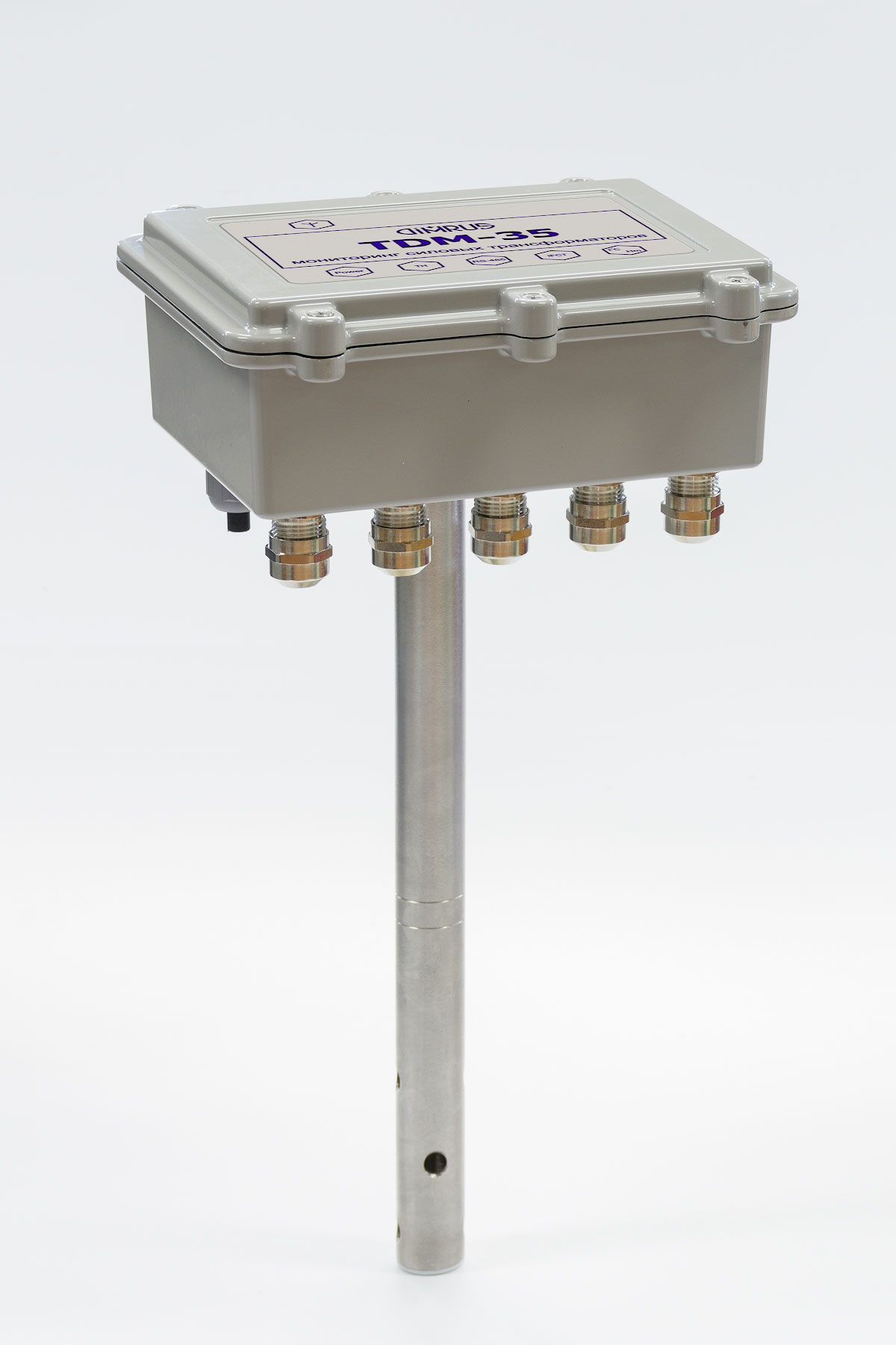
The design of the TDM-35 monitoring system device is similar to that of the TDM-10. The electronics are located in the upper sealed part of the instrument housing. In the lower cylindrical part of the body, which is inserted into the tank (it is similar in diameter to that of the TDM-10 device) there are measuring sensors.
The TDM-35 measuring device is mounted on the top cover of the transformer tank. For this, an adapter flange with a sealing assembly is used, which is similar in design and dimensions to the adapter flange for the TDM-10 device (Figure 2). The adapter flange is installed on any technological cover available on the surface of the transformer tank; the sealing element is a ball valve with a through hole DN of at least 30 mm.
For the primary installation of the adapter flange (at least a ball valve), it is necessary to drain the oil from the transformer tank to the level of the upper tank cover and install the adapter flange. In the future, the installation and dismantling of the TDM-35 measuring device can be carried out without even partial draining of the oil.
If it is not possible to mount the TDM-35 measuring device on the top cover of the transformer tank, then it can be mounted on the side surface of the tank. In this case, the monitoring system will retain its operability and functionality, but the function of the protective relay based on the minimum oil level in the tank will not work correctly.
The wiring when installing the measuring device of the TDM-35 system is simple and inexpensive. Since all the main sensors are combined into one unit, which is already immersed into the oil of the transformer tank at the installation stage, then only four cables should be connected to the measuring device of the system:
- AC/DC power cable.
- Cable from the IFCT-5 sensor for transformer load current monitoring.
- Communication cable, if the system uses a wired RS-485 interface.
- Cable for connecting the ambient temperature and humidity sensor.
The antenna of the selected wireless communication interface (Bluetooth or LoRa) is mounted on the device case at the factory and does not require an external cable line to be connected.
The TDM-35 System Specification
| Monitored transformer HV, kV | up to 35 kV |
| Load current value (CT) circuit), А | 0 ÷ 5 |
| Output (input) transformer voltage, V (AC) | 110 / 220 |
| Temperature-in-the tank monitoring range, ℃ | -40 ÷ +125 |
| Moisture-in-oil content monitoring range, ppm | 0,63 ÷ 63,69 |
| Moisture in the solid insulation, % | 0 ÷ 10 |
| Discharge activity, dBm | -60 ÷ -8 |
| Monitored vibration frequency range in the tank, Hz | 10 ÷ 1000 |
| Oil level in the tank relay activation, mm | ±20 |
| The dimensions of the box with electronics W*D*H, mm | 400*200*170 |
| The dimensions of the cylindrical part with in-built sensors D*H, mm | 30*250 |
| Device weight, kg | 2,5 |
| Operation temperature, ℃ | -40 ÷ +85 |
| Supply voltage, V (AC) | 110÷240 |
| Power consumption, W, not more | 5 |
For the most efficient use of the monitoring results, it is recommended to use the INVA software, which implements the functions of managing the transformer operation and maintenance at SCADA level.
The Defects of Oil-filled Transformers Diagnosed by TDM-10 and TDM-35 Monitoring Systems
The parameters monitored by the TDM-10 and TDM-35 monitoring systems are summarized in the table below.
| System | Transformer type and voltage | Monitored Parameters | ||||||||||||||||||||||||||||||||||||||||||||||||||||||||||||||||||||||||||||||||||||||||||||||||||||||||||||
Load current |
Transformer temperature |
Moisture in oil content |
Moisture in solid insulation |
Oli level |
Discharge activity |
Ambient temperature and humidity |
Pressure in the tank |
Vibration |
||||||||||||||||||||||||||||||||||||||||||||||||||||||||||||||||||||||||||||||||||||||||||||||||||||||
| 1 | 2 | 3 | 4 | 5 | 6 | 7 | 8 | 9 | ||||||||||||||||||||||||||||||||||||||||||||||||||||||||||||||||||||||||||||||||||||||||||||||||||||||
| TDM-10 | Oil-filled transformers of up to 15 kV | - | 1 | 1 | - | 1(1) | 1 | - | 1(2) | 1 | ||||||||||||||||||||||||||||||||||||||||||||||||||||||||||||||||||||||||||||||||||||||||||||||||||||
| TDM-35 | Oil-filled transformers of up to 35 kV | 1 | 1 | 1 | 1 | 1(1) | 1 | 1 | 1 | 1 | ||||||||||||||||||||||||||||||||||||||||||||||||||||||||||||||||||||||||||||||||||||||||||||||||||||
Notes:
(1) - monitoring system protective function
(2) - additional option for TDM-10 system
These monitoring systems differ in the number and type of sensors; as a result, they have different reliability of the diagnostic conclusions obtained. A more complex system with more sensors is more expensive but more informative.
The list of the most common local defects of oil-filled transformers, detected by the built-in diagnostic expert system, is given in the table.
| Defect | Parameter (see table above) | Reliability | |
| TDM-10 | TDM-35 | ||
| 1. Transformer Winding Insulation | |||
| Transformer tank oil dielectric strength monitoring by the presence of dissolved water in it | 2, 3 | ++ | ++ |
| Moisture content monitoring in the solid insulation of transformer windings | 2, 3, 4 | - | ++ |
| Assessment for the winding insulation natural aging based the transformer operating time | 1 | ++ | ++ |
| Monitoring of temperature excesses leading to accelerated winding insulation aging | 1, 2 | + | ++ |
| Identification of local defects in the transformer insulation by partial discharges | 6, 7 | + | + |
| Determining the defect type, its degree of development and danger | 6, 7 | + | + |
| 2. Transformer Core | |||
| Transformer core pressing force monitoring by the spectrum of the vibration signal | 1, 9 | ++ | ++ |
| Monitoring of short-circuits in the transformer core | 1, 2, 6, 9 | ++ | ++ |
| 3. Transformer Mechanical Structure Condition | |||
| Transformer structure integrity monitoring by the spectra of vibration signals | 9 | ++ | ++ |
| Transformer cooling efficiency assessment by tank and air temperatures and load current | 1, 2, 7 | - | ++ |
| 4. Transformer Operation and Service Management | |||
| Transformer condition monitoring by its «digital twin» parameters | 1 – 9 | + | ++ |
| Transformer condition determination of the rate determination and its residual life assessment | 1 – 9 | ++ | ++ |
| Planning the timing and scope of service and repair work | 1 - 9 | ++ | ++ |
The reliability of the defect revelation in the table is illustrated as follows:
(++) – rather high reliability;
(+) – relatively low reliability.
For each of the three monitored transformer subsystems: for the insulation system, for the transformer core and for its mechanical structure, the local mathematical models are built in the monitoring system firmware.
By combining the three local models the final mathematical model of the transformer, its «digital twin», is built.