


Test-PD – Device for Effective Diagnostics of High-Voltage Cables, Terminations and Joints
The compact portable Test-PD device is designed for effective condition examination of terminations and joints in the medium voltage and high voltage cables, 6 kV and above.
The device is easy to use thanks to the in-built expert system, which automatically forms the diagnostic reports. This makes it possible to use the device by the staff with no special training.
To diagnose the cable/termination/joint condition it is necessary just to bring the device close to it. The data received will be immediately displayed as four colored histograms and the picture of the cable crosssection.
The Test-PD Device Specifications
The Test-PD device have 5 in-built sensors of different types:
- Ultrasonic (AC) sensor for partial discharge measurement.
- High-frequency partial discharge sensor.
- Capacitive VHF partial discharge sensor.
- Non-contact pyrometer for cable/termination/joint temperature measurement.
- Current sensor for power synchronization.
The data from the sensors is enough to carry out the effective condition diagnostic and to locate the defect in the cable/termination/joint insulation.
Partial discharge are measured in three frequency ranges: ultrasonic (AC), HF and VHF, to reveal the partial discharges from the defects of different types, which behave in a different way in different frequency ranges.
The non-contact pyrometer is for temperature measurement and locating the defect zones with higher temperature in a cable/termination/joint.
The current sensor synchronizes the measurements with the current in the cable, which is necessary for cable/termination/joint insulation defect type specification.
The Test-PD Device Operation
To analyze the high-voltage cable/termination/joint condition bring the device close to it. All the sensors are installed in the horizontal raw form the right to the left the in the middle of the device back. To enhance the acoustic sensor and pyrometer sensitivity there holes opposite them in the device case. All the rest of the sensors measure through the radio-transparent device case.
Moving the Test-PD device along the cable/termination/joint surface it is possible to find the spots with the highest partial discharge activity and the highest temperature. These spots are the spots with the defects in the cable/termination/joint insulation.
The data received from the sensors about the partial discharge intensity and amplitude obtained in various frequency ranges is illustrated on the device screen in digital form and in the form of colored bar graph histograms.
To increase the information content, in the device screen there is a schematic cross-section of the cable, on which the registered partial discharges are displayed as stylized flickering sparks.
The number of the sparks and their brightness depend on the partial discharge intensity in this part of the cable/termination/joint. The partial discharges can be shown in the high-voltage cable, in the insulation or in the cable shield.
The measured high-voltage discharges which the expert system distinguished as noises are shown as flickering sparks but not in the cable drawing, but around it. The growth of the partial discharge activity is accompanied by the sound.
The cable/termination/joint surface temperature is also displayed digitally in the form of a separate histogram.
If the Test-PD current sensor measured current in the cable, then “N” is displayed and the diagnostics synchronizes to the power current sinusoid phase.
If there is no synchronization to the power current, then “G” is displayed and the diagnostics is done with reference to the inbuilt generator.

Partial Discharge Distant Measuring and Measuring in the Live Parts of the Equipment
Sometimes the cable/termination/joint is located on the ground and are easy to reach for the stuff to examine with the Test-PD device.
But often there are cases when there is no direct access to the cable/termination/joint, for example, when the cable is laid on a high overpass, but the examination is necessary. For such cases the TestPD device has some design and software features.
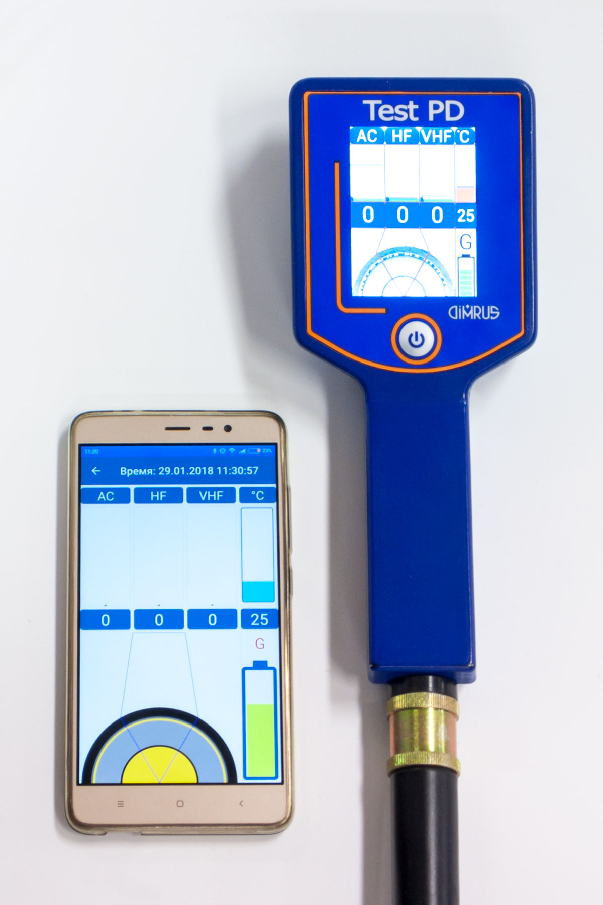
Firstly, the Test-PD device has got a Bluetooth radio interface, via Bluetooth the measurement results and the expert system data can be shared with some other devices with the same interface, such as smartphone, tablet, etc. The information on their screens will be displayed in the same form as in the device screen.
Secondly, the Test-PD device can be mounted on the end of a standard insulating rod. In this case the device is attached to the rod and measurements start. This allows partial discharge measurement in the remote cable/termination/joint and live equipment. The measurement results can be displayed in the smartphone or tablet screen.
The Test-PD Device Specifications
| PD measurement ranges | 2÷100 MHz 0,1÷2 MHz 40 kHz |
| Temperature measurement range, °C | -40 to +120 |
| Wireless interface | Bluetooth 4.1 |
| Operation temperature, °C | -20 to +40 |
| Battery life, hours | 10 |
| The device dimensions and the case material, mm | 205 x 85 x 75, plastic |
| The device weight, kg | 0,3 |
| Transportation case dimensions, mm | 205 x 85 x 75 |
| The weight of the set, cased, kg | 2,0 |