CDM – PD Cable Insulation Monitoring System
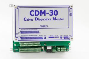
«CDM» monitoring system (Cables Diagnostics Monitor) is for on-line monitoring of cable insulation condition of up to 45 cables with the rated voltage of 6-220 kV. Every monitored cable should be connected to the same switchgear.
The use of «CDM» multichannel monitoring system allows reducing the overall expenses on the monitoring and diagnostics system, estimated for one monitored cable. Besides, it allows more effective high-voltage noise rejection, which is very significant for large switchgears.
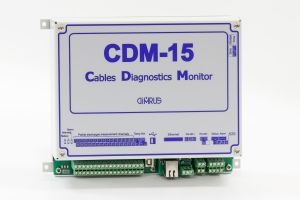
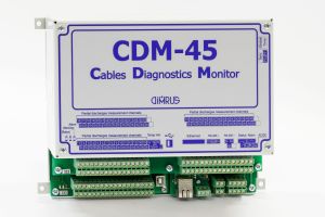
«CDM» system is used for periodic on-line monitoring of cable insulation condition of up to 45 cables in combined cable assembly (switchgear). Optionally the monitoring systems for 15 or 45 cables are available.
«CDM» is for monitoring the condition of the power cable insulation, joints and terminations using PD measurement and analysis, which has the highest possible sensitivity for the defect diagnosis of any insulation type.
The features of the «CDM» system are the following:
- simultaneous condition monitoring of up to 45 cables connected to one place;
- continuous cable condition monitoring in all the critical operating modes;
- analyzing the received information, making diagnostic reports and giving the recommendations for the further cable operation.
«CDM» system has the following diagnostic functions
- «CDM» continuously monitors the power cable insulation by using the method of PD level measurement and PD distribution analysis. The system determines the type of the insulation defect and analyzes its degree and the risks for the further operation.
- «CDM» automatically locates the defect places in joints and cables on-line, under the operating voltage.
Online Cable Monitoring with «CDM» System
«CDM» is designed to monitor the cable insulation online, and it is completely automatic. The «CDM» device built-in memory volume is enough for storing of PD measurements' results for a long time. The received information and the diagnostic reports are uploaded on-line to SCADA.
The on-line diagnostics of the cable insulation condition is done inside the device by the built-in algorithms. If the critical PD levels are reached, the red LEDs light up on the «CDM» device enclosure. The PC program automatically generates the condition reports for all the monitored cables.
For cable condition monitoring with «CDM» system it is necessary to do some preparatory procedures.
First, «RFCT-7» PD sensors should be installed on the grounded shield of the cables planned for monitoring. The sensors are connected to the «CDM» with coaxial cables of one and the same length.
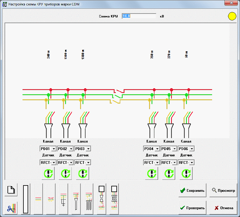
Using «CDM» in the automatic mode requires pre-forming of a circuit configuration scheme of the monitored cable assembly. This configuration scheme is created on PC and is downloaded into the device firmware before monitoring starts.
The circuit configuration scheme is easily drawn by special design software. While creating the configuration scheme, all the information necessary for defective cable detection, its condition assessment, specifying the insulation defect type and its danger is entered into the program.
«CDM» System Basic Algorithms
The most difficult problem of PD measuring in high-voltage cables is noise rejection; the noises reduce the system diagnostic sensitivity in tens or even hundreds of times.
The "CDM" system has the firmware for noise rejection. It includes the following algorithms:
- The complex analysis of the pulse origin time and supply voltage phase.
- «Time of arrival», i.e. noise rejection by the pulse time of arrival from different cables, in nanoseconds.
- Amplitude PD noise rejection is used for deleting pulses from adjacent cables.
- The analysis of each pulse's frequency characteristics allows sorting the repetitive PD pulses out from the accidental pulse noises.
- Temperature and humidity measurement near the monitored switchgear, which also adds to the diagnostics validity.
The second important task of the built-in algorithms is specifying the type of the cable insulation defect and assessing its danger. The built-in «PD-Expert» system allows assessing PD level and specifying the type of the cable insulation defect. «PD-Expert» is even able to separate several similar defects located in different zones of one cable.
«CDM» has the function of defect location. A PD pulse of the insulation defect is used as a probe pulse. If the line has no pulses of sufficient amplitude, the induced noise pulses can be used as probe ones.
There is a built-in «on-line» reflectometer in «CDM», which also expand the diagnostic capabilities of the system.
«CDM» System Delivery Set
- «CDM» device in the protective enclosure with alarm LEDs (optionally)
- a set of PD sensors, in accordance with the specifications
- signal cables 15 meters long for each sensor
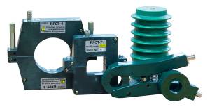
For PD measurements the following sensors are available:
- «RFCT-7» split-core sensors suitable for currents of high-frequency, grounded on the cable shield. The sensors are installed on the ground cables of the shields.
- «TEV» electromagnetic sensors for magnetic installation on the switchgear's enclosures surface. «TEV» sensors are used when «RFCT-7» sensors are impossible to install.
The sensors are chosen in accordance with the cable type and the cables layout in the switchgears.
«RFCT-7» sensor is a split-core sensor with the 34*34 mm inner window. The sensors measure partial discharges in the conductors with the power current of up to 1000 A. They are specially designed for the use in the cable insulation monitoring systems.
If the grounding conductor (or bus) is too thick for «RFCT-7» sensor, then «RFCT-4» split-core sensor with the 67 mm-diameter window can be used.
If «CDM» is planned to monitor the bar insulation, it is necessary to use special «CC» coupling capacitors, which are installed on two ends of the busbar. The «CC» coupling capacitors design allows using them as bar post insulators.
Interfaces in «CDM»:
- RS-485 galvanic isolated interface;
- Ethernet interface for connection to the local network;
- USB interface for the measured data download to PC.
The «CDM» System Specifications
| The number of the monitored cables | up to 45 |
| Operating voltage, kV | > 3 |
| Monitored line length, km | < 4 |
| PD pulses frequency, MHz | 0,5 ÷ 15,0 |
| PD magnitude, pC | 20 ÷ 100000 |
| Accuracy of defect location | ±1% of cable length |
| PC connection | RS-485, Ethernet |
| Power Supply, AC / DC, V | 90 ÷ 260 |
| Operating temperature, °C | -40 ÷ +60 |
| Enclosure dimensions, mm | 700 * 500 * 250 |
| Weight, kg | 20 |


