


GIS-DM – Gas-Insulated Switchgear and HV Cables Insulation Defects Monitoring and Diagnostic System
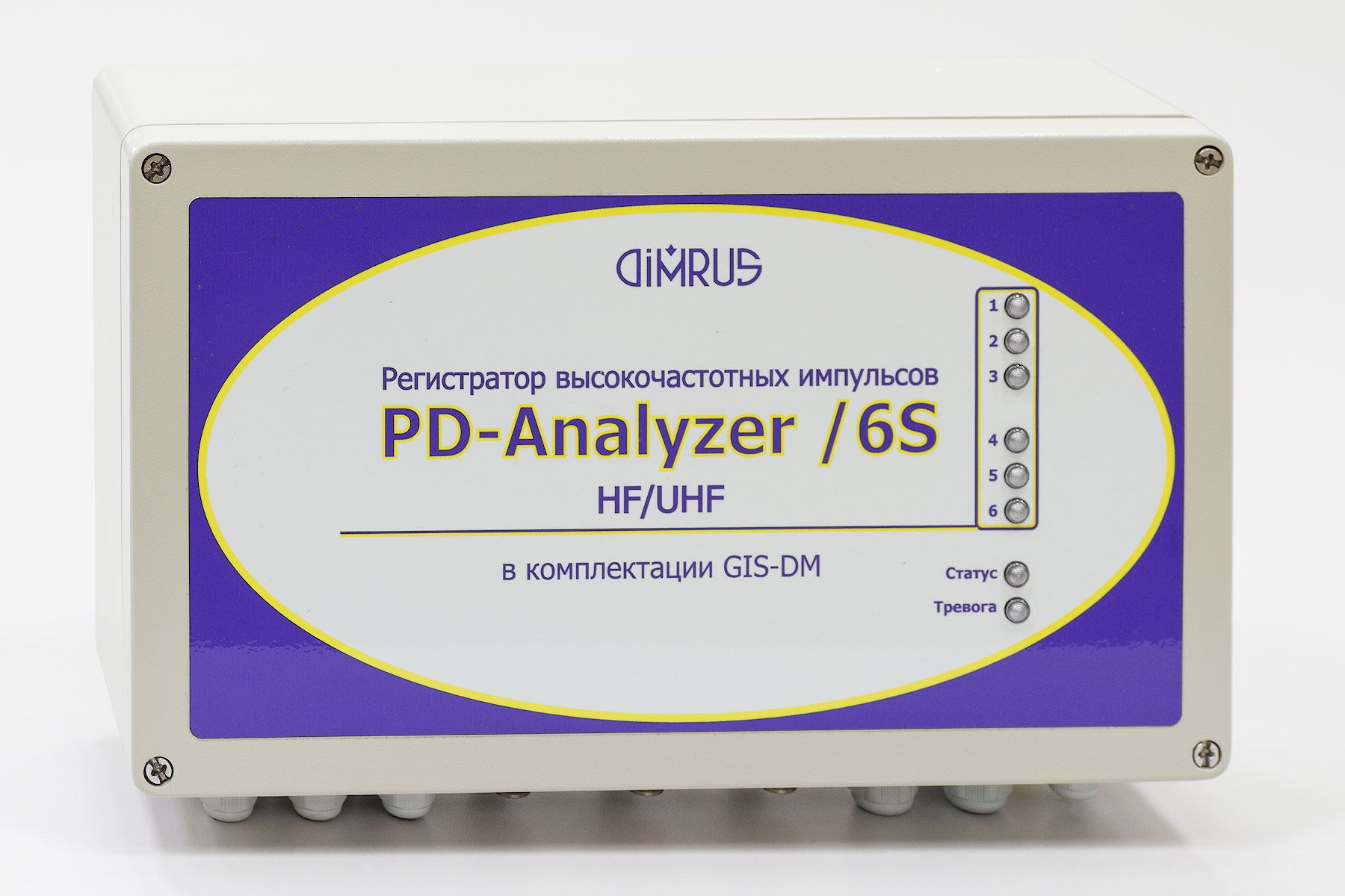
"GIS-DM" monitoring system (Gas-Insulated System – Diagnostic Monitor) is used for online monitoring of gas-insulated equipment, such as Gas-Insulated switchgears (GIS), instrument and power transformers, breakers etc.
The equipment condition essessment by "GIS-DM" is made on the basis of PD measurement in UHF frequency range. This way of PD measuring is the most sensitive and effective for high-voltage (HV) insulation monitroing.
"ACS" and "AES" sensors are used for PD measuring in the Gas-Insulated equipment
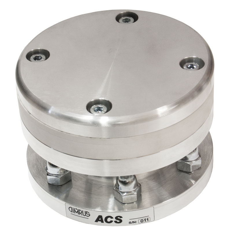
"ACS" high-frequency sensor is an electromagnetic antenna built into the gas-insulated equipment. The sensor is usually installed on internal side of the access covers in GIS. "ACS" sensors should be installed by the Gas-Insulated equipment manufacturer, because it is rather difficult to install the sensors on the operating equipment.
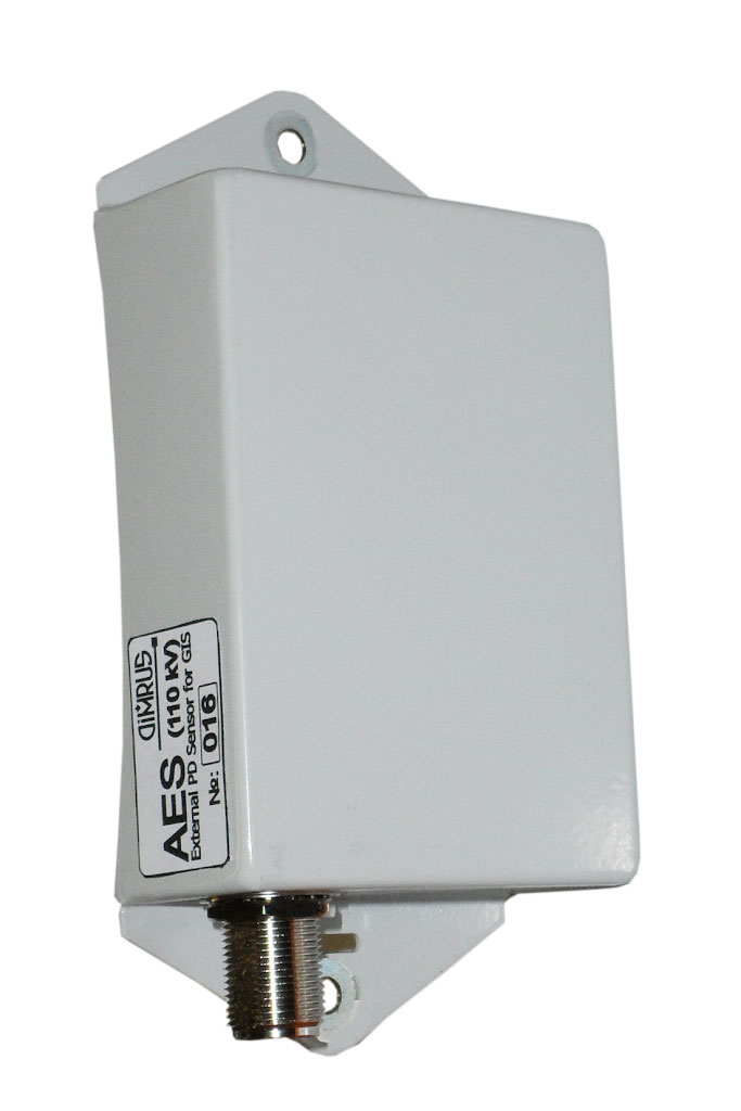
"AES" PD sensor is installed on the external surface of GIS on the radioparent insulating spacer. "ACS" sensor measures the electromagnetic pulses, coming out of insulating gas through the radioparent spacers. This sensor is easily installed either on new or operating equipment.
"ACS" or "AES sensors are connected to the measuring device of "GIS-DM" system by coaxial cables. These cables can't be long because of the considerable UHF signal damping along the cable, which considerably decreases the monitoring system sensitivity.
"GIS-DM" system is based on the most up-to-date technological solutions
The features of "GIS-DM" system are:
Synchronic PD pulse measuring by all the six measurement channels of the "GIS-DM" monitoring system. This feature allows efficient detecting and locating of insulation defects in GIS, by analyzing the time of arrival of the PD pulse to two PD sensors in GIS. Due to this fewer sensors can be used on the monitored equipment.
PD signal measuring in every device channel is taken in two frequency ranges – HF and UHF, so the frequency range is rather wide - from 100 kHz to 1,5 GHz. It allows measuring UHF pulses located inside equipment near the measuring sensor and remote LF pulses.
The important feature of "GIS-DM" system is the specialized software
The software of "GIS-DM" system allows:
- Additional digital processing of the measured data for more efficient noise rejection. For that, such methods as assessing the pulse digital parameters, comparing pulse amplitude and "time of arrival" are used. There is the possibility of defect location by assessing the difference in the time of pulse arrival to each sensor.
- PD measuring in gas-insulated equipment; identifying the defect type and degree on the base of PD measurement by "PD-Expert" software. "PD-Expert" software compares the measured data to the "defect type" database, kept in the device memory, and identifies the type of defect in the GIS insulation.
- Integrating the diagnostic reports into the global monitoring systems which assess the present condition and the remaining life of the whole of the equipment, such as the manufacturing line including the GIS, or the whole of the substation, or even the whole of the energy transmission line. An example of such integrated software for "Smart Grid" systems is "iNVA" software by DIMRUS.
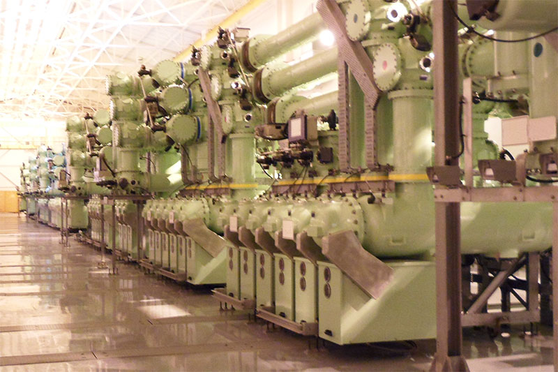
"GIS-DM" System Installation on GIS
One "GIS-DM" device is enough for monitoring of the insulation of one GIS section. In the figure there is example of six "AES" sensors installation (S1-S6) in one section of GIS.
The monitored gas-insulated section consists of cable terminations, a measuring current transformer (CT), a breaker (B), and two breakers (D) for the commutation of the bus sections (C1-C2). The six sensors (S1-S2) provide the GIS insulation condition monitoring, defect location, as well as HV cable insulation condition monitoring.
"CDR-S", "RFCT-4" or "RFCT-7" PD sensors and, if there is the need, temperature sensors can be connected to the measuring device of "GIS-DM" system. It allows PD monitoring in the insulation of high-voltage cables connected to the GIS. Besides, it is possible to see the reflectogramms of PD pulse distribution along the cables and to locate the defects in cables online.
"GIS-DM" Integration into the Multipurpose Monitoring Systems of GasInsulated Substations
The creation of the monitoring systems for big and complex GIS, with several "GIS-DM" devices, demands special of hardware and software for such integration.
The following conditions should be met for several "GIS-DM" devices to be integrated into one monitoring system:
- Synchronization of PD pulse measuring by all the measuring devices by fiber optic; it improves noise rejection and makes the insulation defect location "global".
- Integration of the information given by all the devices in one shared computer for complex analyzing the PD pulses in GIS.
All these diagnostic functions are realized due to synchronization by the fiber optic, accurate within nanosecond or tens of nanosecond, by using GPS/GLONASS signals.
Specifications of «GIS-DM" System
| Rated voltage of the monitored equipment, kV | 6 ÷ 500 |
| The number of PD measuring channels in one device | 6 |
| PD measuring range, MHz | 0,1 ÷ 1500,0 |
| High-frequency pulse amplitude, mV | 1÷10000 |
| Type of PD sensor | ACS, AES |
| The number of "GIS-DM" devices in one monitoring system | Up to 100 |
| The number of temperature measuring channels | Up to 7 |
| The number of air humidity measuring channels | 1 |
| SCADA connection interface | Ethernet, RS-485 |
| Temperature range, °C | -40 ÷+65 |
| System supply voltage, V | AC/DC 120 ÷ 260 |
| "GIS-DM" device dimensions, mm | 400*230*110 |