KMK-500 – Integrated System for 110÷500 kV High-Voltage Cable Monitoring

«KMK-500» system is for integrated on-line monitoring of cable condition, including:
- Monitoring of cable operating modes by distributed temperature sensing.
- Monitoring of cable insulation condition by partial discharge measurement, using high-frequency sensors.
- Monitoring of terminations and joints condition by partial discharge measurement, using acoustic sensors.
- Measurement and analysis of the capacitance leakage currents in cable shields.
Why is cable monitoring necessary?
- Continuous monitoring of cables allows effective monitoring of the cable operating modes by such parameters as temperature and shield currents.
- Defects develop rather quickly in XLPE insulation that is why it is only continuous monitoring that helps to reveal dangerous defects in cables timely.
- The use of monitoring systems prevents unexpected failures.
- The use of the inbuilt monitoring systems minimizes the operational costs of the monitored cables.
«KMK-500» Monitoring System
«KMK-500» (Cable Monitoring Complex) system has the following functions:
- Temperature monitoring of cables by «ASTRO» system with fiber optic, which allows assessment of the cable operation temperatures, diagnostics of the overheated zones and evaluation of the possibility of increasing load on the cable.
- Defect detection in cables and joints at the early stages of their development by partial discharges; defect type determination and defect danger assessment. For this purpose «CDR» device (Cables Diagnostics Relay for cable insulation condition monitoring) and «ADM» device (Acoustic PD Monitor for termination and joints insulation condition monitoring) are used.
- On-line defect location in cable insulation by analyzing «time of arrival» of the direct and reflected PD pulses, by «CDR» device.
- Effective monitoring of capacitive currents and cross currents in the cable shield, which allows correcting the cable operation modes.
«KMK-500» Hardware
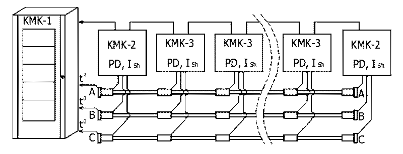
All the equipment of «KMK-500» system is located in the three types of enclosures (cabinets) and communicates by fiber optic. The hardware configuration of the monitoring system depends on the installation place and the monitored cable configuration.
The monitoring system can include:
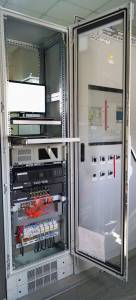
1. «KMK-500/1» multipurpose central cabinet of the cable monitoring system. This cabinet includes an industrial computer with the installed software for integrated cable diagnostics by several methods; there is also the SCADA communication means.
If «KMK-500/1» cabinet is located close to the terminations of the monitored cable, then «ASTRO», «CDR» and «ADM» measuring devices can be installed in «KMK-500/1». If the distance is large enough, then the measuring devices should be installed in the additional «KMK-500/2» cabinet for the signal cables to be shorter.
2. «KMK-500/2» cabinets for local measurements are mounted at the beginning and (for long cables) at the end of the cable.
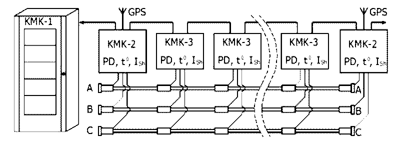
In «KMK-500/2» the «ASTRO», «CDR» and «ADM» measuring devices are usually situated. The information from the «intermediate» «KMK-500/3» cabinets is collected and is uploaded into «KMK-500/1» cabinet by fiber optic. For the signal measurements to give more informative results, the measurements in all the «KMK-500/2» cabinets are synchronized by GPS.
3. «KMK-500/3» intermediate measuring cabinet is used for joints monitoring. The cabinet is mounted near the cable joints, as a rule in the cable chambers.
In «KMK-500/3» cabinet «ADM» devices for joints monitoring and the sensors for monitoring currents in cable shield are usually installed.
«KMK-500» Software
The effectiveness of the monitoring system is largely dependent on the use of special software: the more automated expert algorithms are implemented in the software the higher is the practical significance of the monitoring system.
«KMK-500» cable monitoring system includes «iNVA-KMK» software, which is composed of:
- Server software for primary measurement synchronization and the module for data collection from remote sensors and monitoring devices.
- The software for processing, visualization, storing and archiving of the primary and diagnostic information of the cable line condition.
- «KMK-Expert» automated expert software, which makes an integrated diagnostic report about the cable condition and the revealed defects on the base of all the information received from all the devices and intermediate diagnostic reports.
- A set of protocols (IEC 61850) and interfaces for communicating with SCADA.
Monitoring System Configuration
The whole set of «KMK-500» system provides cable monitoring by three methods, they are:
- operation mode monitoring by cable temperature;
- cable condition monitoring and defect diagnostics by PD measurement and analysis;
- cable condition monitoring by measuring leakage currents in cable shields.
As a rule, the standard modification of «KMK-500» system is used for monitoring of two high-voltage cables consisting of 6 one-phase cables. If necessary, the modification of the system for one high-voltage cable monitoring (three one-phase cables) can be supplied, as well as for monitoring of three cables and more.
The monitored cable can be up to 8 km long, the length is determined by the temperature monitoring subsystem operation. For longer cables monitoring - up to 16 km – the «ASTRO» system with more powerful laser should be used.

In the scheme above «ASTRO» monitoring system is installed in «KMK-500/1» cabinet. If the distance from the cabinet to the monitored cable is considerable, then «ASTRO» is installed in «KMK-500/2» cabinet, together with the PD and currants-in-shield monitoring systems.
«KMK-500/3» joints insulation monitoring cabinets are situated along the cable; they are united in one information system by fiber optic. The same fiber optic line is used for PD measurement synchronization, which is necessary for precise defect location in cable.
The location of the defect in the cable insulation is identified by analyzing the time of PD pulse arrival to the two measuring devices, situated at both the ends of the monitored interval of the cable.
The monitoring system for insulation defect diagnostics can be supplied as a separate system. This variant of the system includes PD measuring devices and currents-in-shield measuring devices only. Such a system also provides temperature monitoring, but not of the whole cable, but the terminations and joints only.

Partial discharge measurement in the «KMK-500/2» cabinets can be synchronized not only by fiber optic, but by GPS – this function is supported by «CDR» devices. GPS synchronization allows not to use the intermediate «KMK-500/3» cabinets and the connection fiber optic for comparatively short cables.
The «KMK-500» monitoring system configuration is specified individually in each case. The configuration depends on the customer requirements and the cable line configuration.
«KMK-500» System Specifications
| Monitored cable operating voltage, kV | Up to 500 |
| The number of monitored cables | 1 and more |
| Cable length, km | Up to 16 |
| Optic Temperature Monitoring by «ASTRO» | |
| Temperature measurement accuracy, °C | 1 |
| Spatial resolution, m | 1 |
| Temperature measurement cycle, sec | 5 |
| PD Measurement by «CDR» | |
| PD measurement range, MHz | 0,1 ÷ 45,0 |
| Measuring channel sensitivity, pC | 10 and more |
| Measurement synchronization | GPS, fiber-optic |
| The number of measuring channels in one device | 6 |
| PD Measurement by «ADM» | |
| PD measurement range, MHz | 30 ÷ 300 |
| Measuring channel sensitivity, pC | 50 |
| The number of measuring channels in one device | 9 |
| Currents-in-shield Measuring | |
| 50 Hz current measurement range, A | 1 ÷ 1000 |


