


TDM-10S / TDM-35S – Monitoring Systems for Power Transformers of up to 35 kV with Solid Insulation
Power transformers with solid winding insulation are increasingly being used in practice. Along with the significant advantages, the operation of such transformers has also revealed a number of specific problems caused by the winding design.
The epoxy compound used to insulate the windings of dry-type transformers can crack due to exposure to high temperatures and mechanical stress, which can ultimately result in insulation gaps breakdown and transformer damage.
For timely defect detection and their development monitoring it is necessary to monitor the two most important parameters: the transformer windings operating temperature and the high-frequency discharge activity development in the windings, which almost always accompanies the occurrence of defects in solid insulation.
To continuously monitoring these parameters, DIMRUS has developed two diagnostic systems: the TDM- 10S monitoring system for power distribution transformers of up to 15 kV with solid insulation, as well as a more complex and efficient the TDM-35S system for the transformers of up to 35 kV.
1. The TDM-10S Monitoring System for Transformers of up to 15 kV with Solid Insulation
The TDM-10S monitoring system is designed for the power transformers of up to 15 kV with cast epoxy winding insulation monitoring.
The TDM-10S system uses several complementary diagnostic methods, for each of them specialized sensors are used:
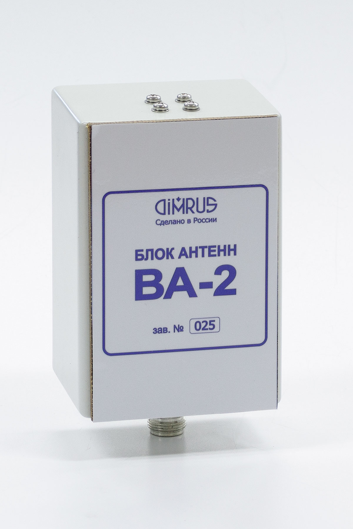
Winding insulation condition monitoring by discharge activity monitoring in the defect zones. For this purpose, the BA-2 electromagnetic antenna (sensor), which is located inside the protective enclosure of the transformer, is used. The channel for discharge measuring and processing in the device is designed so that it measures not only classical partial discharges, which have a relatively small amplitude, but also more powerful discharges, which occur at later stages of insulation defect development and usually precede an emergency breakdown. The BA-2 sensor operates in UHF range; therefore it has good sensitivity and high noise immunity.
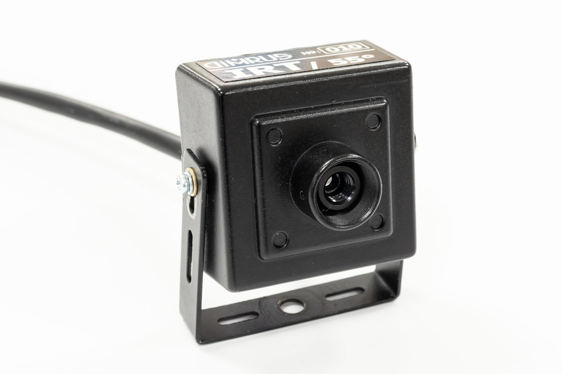
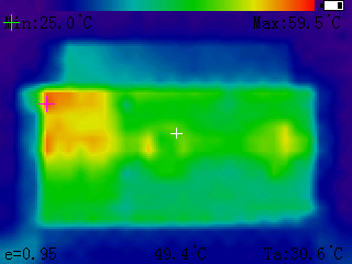
Transformer temperature monitoring and analyses. For remoted temperature monitoring of the transformer windings and core the IRT sensor is used in the TDM-10S monitoring system. The IRT sensor is a simple thermal imager with a resolution of 24 * 36 zones, which is quite enough for determination and localization of the most heated point of the windings and the core of the monitored transformer. The linear dimensions of the winding temperature monitoring elementary zones are determined by the sensor remoteness from the transformer, since the standard measurement angle for this sensor is 110 angular degrees. Instead of the IRT sensor, a standard contact Pt-100 sensor can be included into the TDM-10S delivery set. But in this case the efficiency of the system for winding and core temperature monitoring will significantly decrease, since the contact sensor can monitor the temperature of only one spot.
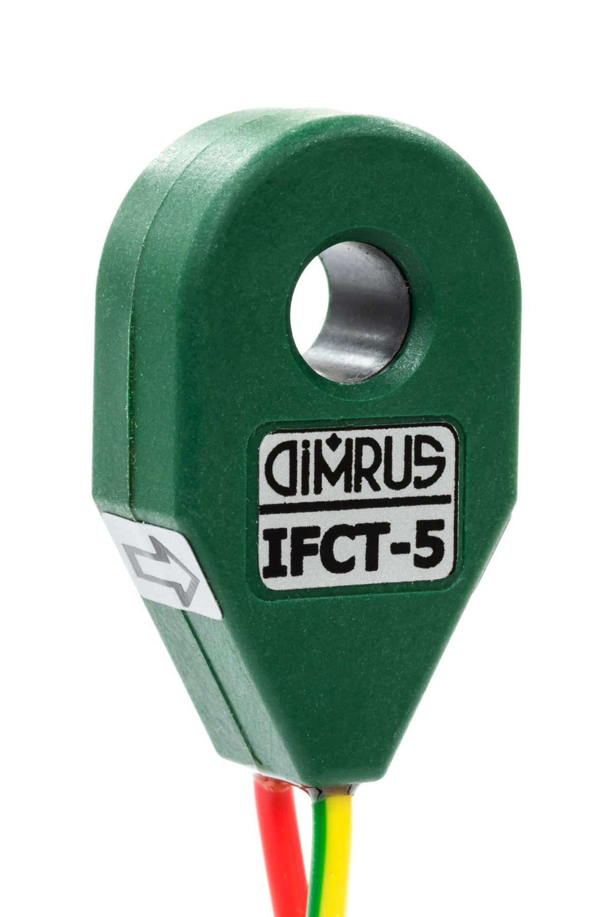
Transformer load on-line monitoring is carried out by the IFCT-5 ring current sensor, which is mounted on the conductors of the measuring current transformers secondary circuits. Such installation does not affect the current transformer operation. Knowing the transformer operation load allows you to more correctly assess its effect on the temperature conditions of the windings and core and identify signs of defective conditions.
Ambient temperature and humidity monitoring allows to assess the winding cooling efficiency, to reveal surface contaminations and solid insulation local damage. The combined consideration of the transformer load, winding temperature, ambient temperature and humidity, and discharge activity makes it possible to quickly build a digital model of the transformer winding solid insulation aging and determine the insulation residual life.
Transformer vibration monitoring. The vibration sensor is installed on the lower part of the transformer core, which makes it possible to carry out operational diagnostics of the transformer structure condition, to detect weakening and mechanical defects of various nature. This information is also taken into account when determining the transformer residual life. Vibration sensor is an option for the TDM-10S monitoring system.
The TDM-10S device and sensors installation in the transformer
The TDM-10S device is installed next to the monitored power transformer. All the sensors of the monitoring system are mounted next to the monitored transformer, and only the optional vibration sensor is mounted directly on the transformer itself. This greatly simplifies the installation of the TDM-10S monitoring system. During installation, it is necessary to use the shortest possible signal cables from the sensors to the device in order to reduce the influence of possible electromagnetic interference and overvoltages.
The IRT remote temperature sensor is mounted inside the transformer protecting enclosure so that it can directly, not through the protective grid, control the temperature of the windings of all three phases and the core of the solid insulation transformer. The sensor is installed in the center of the transformer, the distance from the sensor to the transformer windings should be approximately 40% of the transformer width. Next to the IRT temperature sensor, the ВА-2 electromagnetic antenna is installed for remote monitoring of discharge activity, it is directed to the windings of the monitored transformer.
The IFCT-5 ring load current sensor is mounted on the measuring current transformer secondary circuit conductor. Using information from this sensor, the temperature of the most heated inner part of the winding is calculated, which is important for monitoring the residual life of the solid insulation of the windings.
The climate sensor (ambient temperature and humidity sensor) does not need to be additionally connected to the device when installing the system on site: the sensor is installed in the device casing in a separate cable gland at the factory (the sensitive element of the sensor protrudes slightly from the cable gland) and is already connected to the measuring device PCB.
The wireless communication interface antenna selected when ordering the monitoring system (optionally it can be either Bluetooth or LoRa) is also pre-mounted in the upper part of the measuring device and does not require any cable connection.
The TDM-10S system communication interfaces
Like all the monitoring systems for power transformers of up to 35 kV manufactured by DIMRUS, the TDM-10S system, after installation, is easily integrated into the substation or enterprise SCADA using the built-in communication interfaces:
- Wired galvanically isolated RS-485 communication interface. This interface has good communication rate and noise immunity, but requires a communication cable to be laid through the substation.
- Bluetooth wireless interface. This interface is especially convenient when the monitoring system is used autonomously, when information about the transformer condition is not transmitted into SCADA, but is periodically read by the personnel with a standard smartphone or tablet with the appropriate software. The antenna of this communication interface is mounted on the upper side of the monitoring device housing in the protective cap.
- LoRa wireless communication interface (LoRa Wan). The LoRa range is as long as several kilometers. The second advantage of the LoRa interface is the use of double encryption of information in it. The most significant drawback of the LoRa interface is its low bandwidth: one packet of information contains only a few tens of bytes. Usually this can only be integral information about the monitored transformer condition.
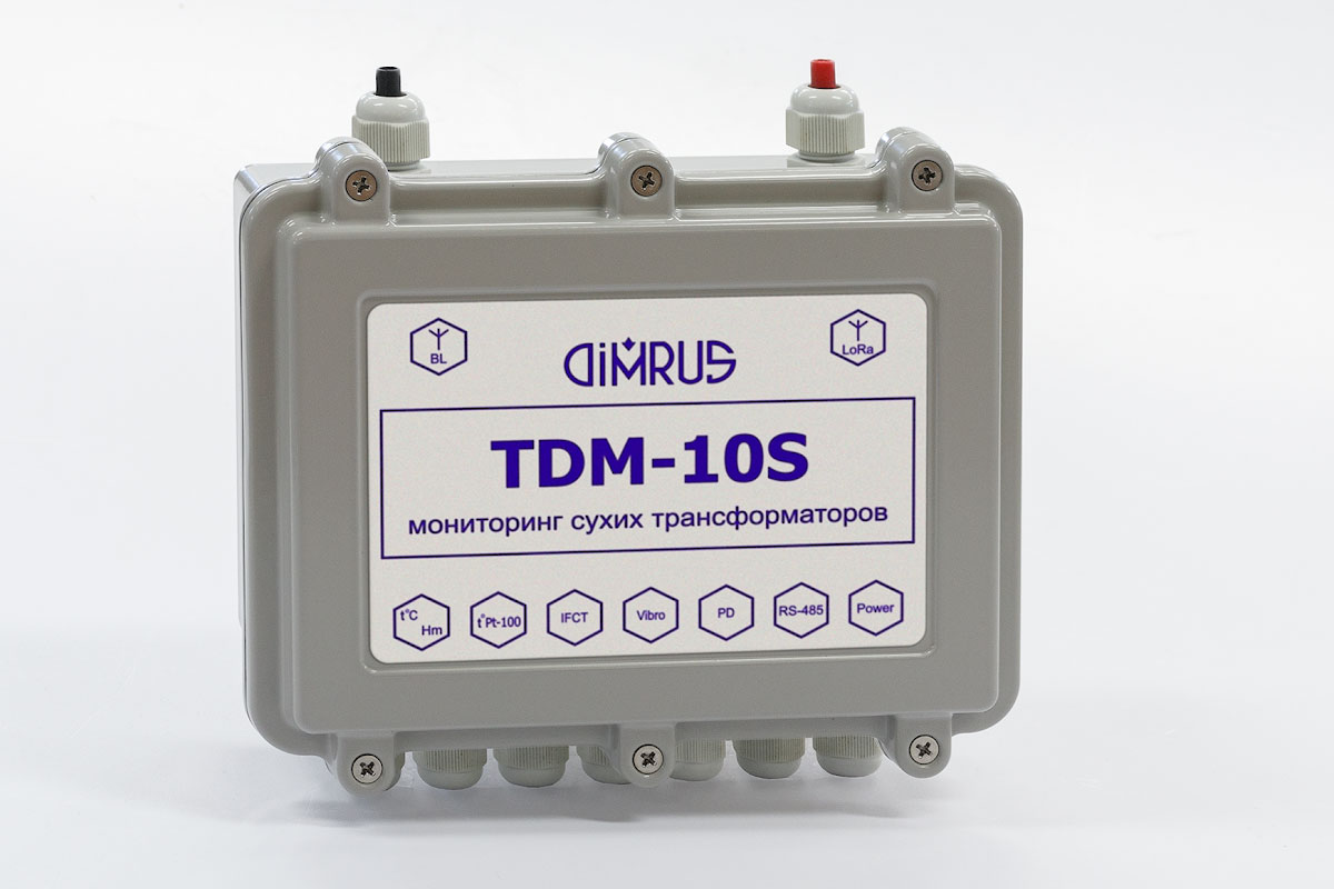
On the TDM-10S device cover three colored LEDs are installed to illustrate the monitoring system performance and the current transformer condition - normal, warning, alarm. The corresponding LED lits up after assessing the transformer condition by the monitoring system. The TDM-10S monitoring system measuring device is supplied in a sealed protective metal case. The device is mounted next to the monitored transformer, usually on the outer surface of the protective housing.
The TDM-10S system device can also be mounted inside the protective enclosure of the transformer, but in this case it will be more difficult to ensure the temperature necessary for the built-in electronics operation and to organize the reliable operation of wireless communication interfaces for transmitting data into SCADA.
The TDM-10S System Scope of Supply
| The TDM-10S device cased | 1 |
| The ВА-2 sensor (UHF antenna) | 1 |
| The IRT remote temperature sensor | 1 |
| The Pt-100 contact temperature sensor (option) | 1 |
| The IFCT-5 load current sensor | 1 |
| The Pt-100 ambient temperature sensor | 1 |
| The SHm-1 humidity sensor | 1 |
| Vibration sensor (option) | 1 |
| Connection cables for the sensors (set) | 1 |
| Technical documentation | 1 |
The TDM-10S System Specification
| Monitored transformer HV, kV | 6 ÷ 15 |
| Load current monitoring is the TT circuit, А | 5 |
| Monitored temperature range, ℃ | -55 ÷ +150 |
| Discharge activity range, dBm | -60 ÷ -8 |
| Transformer core vibration range, Hz | 10 ÷ 1000 |
| Case dimensions, L*W*H, mm | 200*170*77 |
| Device weight, kg | 2 |
| Operation temperature, ℃ | -40 ÷ +65 |
| Supply voltage, V (AC/DC) | 110÷240 |
| Power consumption, W, not more | 5 |
2. The TDM-35S Monitoring System for Transformers of up to 35 kV with Solid Insulation
The TDM-35S monitoring system is designed for condition monitoring and operation management of power transformers of up to 35 kV with cast epoxy winding insulation.
Compared to the TDM-10S monitoring system, this system is more efficient due to the use of additional sensors and a more advanced expert system for assessing the transformer condition and diagnosing transformer defects.
To monitor the current transformer condition in the TDM-35S system, several diagnostic methods are implemented, the results of which complement each other:
- Transformer load monitoring by the IFCT-5 sensor.
- Temperature measurement by IRT remote sensor, described above in relation to the TDM-10S monitoring system. As an option, one to four Pt-100 contact temperature sensors can be used in the TDM-35S system. In any case, the temperature monitoring function of the TDM-35S system allows not only to monitor the temperature of the windings and the core, but also to manage the cooling system operation. When the winding temperature exceeds the specified threshold values, the TDM-35S system device can sequentially turn on the output relays controlling the two groups of transformer cooling fans.
- Transformer winding insulation monitoring by PD measurement and analysis in UHF frequency range by BA-2 sensor. The expert system diagnostic algorithms of the TDM-35S software make it possible to determine the insulation defect type, and to assess the defect danger for the transformer further operation. The system can partially localize the defect by analyzing the difference in the PD time of arrival to different sensors.
- The analysis of the power transformer operation with regard to the ambient temperature and humidity measured with the complex sensor, allows us to evaluate the transformer cooling system efficiency and predict a decrease in the insulation residual life.
- Monitoring the transformer mechanical condition by vibration parameters. The vibration sensor of the monitoring system is usually mounted on the bottom frame of the transformer core, close to the core. Based on the analysis of integral parameters and vibration signals spectra in the built-in expert system, various electromechanical defects in the transformer design are diagnosed.
The set of the monitored parameters, expanded in the TDM-35S compared to the TDM-10S system, allows you to more correctly determine the winding insulation residual resource and calculate the optimal time for repairs of the entire transformer.
TDM-35S System Installation in the Transformer
The TDM-35S device is installed next to the monitored transformer. All primary sensors of the TDM-35S system are mounted directly on the transformer. When installing the system, it is necessary to use the shortest possible cables from the sensors to the device to reduce electromagnetic noises.
The sensor installation depends on the power transformer design; this is especially important for the UHF PD sensors with which the state of the cast compound insulation is monitored and the defects are located.
Two BA-2 UHF antennas are located on both sides of the dry-type transformer. They are directed to the transformer windings, for which they are mounted inside the transformer protective fencing or on additional racks.
The third BA-1 UHF non-directional antenna is located on top of the protective fencing and is designed to measure the external electromagnetic noises. Synchronous comparison of the three antennas’ parameters allows to successfully reject the external high-frequency noises and even to locate the insulation defects.
The ring load current IFCT-5 sensor is mounted on the measuring current transformer secondary circuit conductor. Using information from this sensor, the temperature of the most heated part of the winding is calculated, which is important for predicting the transformer windings solid insulation residual life.
The TDM-35S System Communication Interfaces
Like all the monitoring systems for 6-35 kV power transformers manufactured by DIMRUS, the TDM-35S system, after installation, is easily integrated into the substation or enterprise SCADA using the built-in communication interfaces:
- Wired galvanically isolated RS-485 communication interface. This interface has good communication rate and noise immunity, but requires a communication cable to be laid through the substation. This interface is always implemented into the device.
- Bluetooth wireless communication interface (option). This interface is especially convenient for autonomous use of the monitoring system, when information about the transformer current state is periodically read by personnel via a smartphone or a tablet. The Bluetooth antenna is mounted on the top of the TDM-35S measuring device housing.
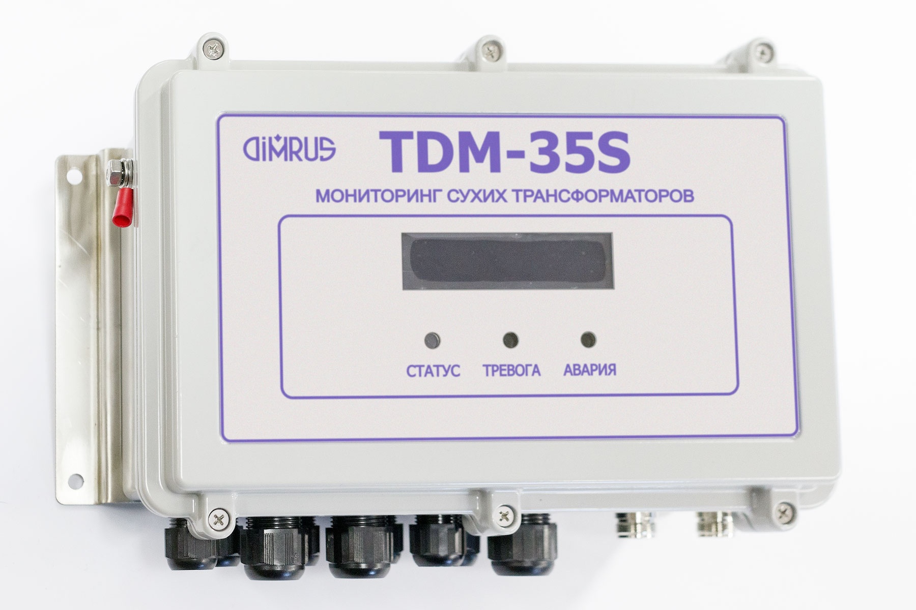
To display the information about the monitoring system operating modes and the transformer condition, the following indications and relays are used in the TDM-35S system:
- Three colored LEDs on the device cover, illustrating the transformer condition - normal, warning, alarm.
- The screen for displaying the information about the critical values and the detected defects.
- Two alarm relays informing about the monitoring system condition and the monitored transformer emergency condition.
The system additionally has two relays designed to control the transformer cooling system fans on the base of winding temperature data.
The TDM-35S Device Installation
As a standard, the TDM-35S measuring device is supplied in a sealed protective metal case. In this case the device can be mounted next to the monitored transformer without any additional protection.
If it is planned to mount the monitoring system on the territory of an open substation, then it is necessary to use of an outdoor cabinet to protect the equipment from external climatic influences. In this case, there is no need to use a sealed case for the device itself, it is enough to use a cheaper metal case.
The TDM-35S System Scope of Supply
| The TDM-35S device cased | 1 |
| The ВА-1 and ВА-2 sensor (UHF antenna) | 2+1 |
| The IPT remote temperature sensor | 1 |
| The Pt-100 contact temperature sensor (option) | up to 4 |
| The IFCT-5 load current sensor | 1 |
| The Pt-100 ambient temperature sensor | 1 |
| The SHm-1 humidity sensor | 1 |
| Vibration sensor (option) | 1 |
| Connection cables for the sensors (set) | 1 |
| Technical documentation | 1 |
The TDM-35S System Specification
| Monitored transformer HV, kV | 10 ÷ 35 |
| Load current monitoring is the TT circuit, А | 5 |
| Output (input) transformer voltage, V | 220 |
| Monitored temperature range, ℃ | -55 ÷ +150 |
| Discharge activity range, dBm | -70 ÷ 0 |
| Transformer core vibration range, Hz | 10 ÷ 1000 |
| The number of transformer cooling system relays | 2 |
| Case dimensions, L*W*H, mm | 280*210*100 |
| Device weight, kg | 3,5 |
| Operation temperature, ℃ | -40 ÷ +65 |
| Supply voltage, V (AC/DC) | 110÷240 |
| Power consumption, W, not more | 10 |
3. Diagnostic and Predictive Analytics implemented in TDM-10S and TDM-35S Systems for Dry-Type Transformer Monitoring
To organize diagnostic monitoring of dry-type transformers, DIMRUS offers the monitoring systems of two types, which differ in the number sensors used to monitor the record the transformer parameters. As a result, the systems differ in information content and reliability of the results obtained. The list of parameters monitored is given in the table:
| System | Transformer type and voltage | Monitored Parameters | ||||||||||||||||||||||||||||||||||||||||||||||||||||||||||||||||||||||||||||||||||||||||||||||||||||||||||||
Load current |
Transformer temperature |
Discharge activity |
Ambient temperature and humidity |
Vibration |
Cooling Control |
|||||||||||||||||||||||||||||||||||||||||||||||||||||||||||||||||||||||||||||||||||||||||||||||||||||||||
| 1 | 2 | 3 | 4 | 5 | 6 | |||||||||||||||||||||||||||||||||||||||||||||||||||||||||||||||||||||||||||||||||||||||||||||||||||||||||
| TDM-10S | Dry-Type Transformer of up to 15 kV | 1 | 1 | 1 | 1 | 1 | - | |||||||||||||||||||||||||||||||||||||||||||||||||||||||||||||||||||||||||||||||||||||||||||||||||||||||
| TDM-35S | Dry-Type Transformer of up to 35 kV | 1 | 4 | 3(1) | 1 | 1 | 2(2) | |||||||||||||||||||||||||||||||||||||||||||||||||||||||||||||||||||||||||||||||||||||||||||||||||||||||
Notes:
(1) – discharge activity monitoring and location with three UHF antennas;
(2) – the control of the two groups of cooling fans.
These monitoring systems are designed for diagnostic monitoring of cast resin transformers and differ in the number of primary sensors and their type.
As a result, systems, on the one hand, assess the condition of the transformer with different accuracy, and on the other hand, as a result, they differ in cost. The more sensors used and the more complex the system, the more expensive it is.
The list of the most common local defective states of power transformers with cast resin, detected by the built-in diagnostic expert system, is given in the table.
These monitoring systems differ in the number and type of sensors; as a result, they have different reliability of the diagnostic conclusions obtained. A more complex system with more sensors is more expensive but more informative.
The list of the most common local defects of dry-type transformers, detected by the built-in diagnostic expert system, is given in the table.
| Defect | Parameter (see table above) | Reliability | |
| TDM-10S | TDM-35S | ||
| 1. Transformer Winding Insulation | |||
| Winding insulation natural aging assessment based on the transformer operation time. | 1 | ++ | ++ |
| Temperature excesses monitoring in magnitude and duration, which is often a cause of the early winding insulation aging. | 2 | ++ | ++ |
| Identification of local defects in winding cast insulation by partial discharges. | 3 | + | ++ |
| Insulation defect type, degree and danger identification. | 3, 4 | + | ++ |
| Winding insulation contamination monitoring. | 3, 4 | + | ++ |
| 2. Transformer Core | |||
| Monitoring the winding epoxy insulation blocks integrity by the vibration signal spectrum. | 5 | ++ | ++ |
| Transformer core pressing force monitoring by the spectrum of the vibration signal. | 5 | ++ | ++ |
| Monitoring of short-circuits in the transformer core. | 2, 5 | ++ | ++ |
| 3. Transformer Mechanical Structure Condition | |||
| Transformer structure integrity monitoring by the spectra of vibration signals. | 5 | ++ | ++ |
| Monitoring the presence of overheating zones in the transformer by the temperature gradient of the winding zones. | 2, 5 | + | + |
| 4. Transformer Operation and Service Management | |||
| Transformer condition monitoring by its «digital twin» parameters. | 1 - 5 | + | ++ |
| Transformer condition determination of the rate determination and its residual life assessment. | 1 - 5 | ++ | ++ |
| Planning the timing and scope of service and repair work. | 1 - 5 | ++ | ++ |
The reliability of the defect revelation in the table is illustrated as follows:
(++) – rather high reliability;
(+) – relatively low reliability.
The most important result of the TDM-S monitoring systems is the information on the possibility of further equipment operation and the optimal timing of repair and service work.
For each of the three monitored transformer subsystems - for the insulation system, for the transformer core and for its mechanical structure, adaptive mathematical models («digital twins») of the condition development are built in the expert software of the monitoring system.
The final mathematical model of the entire transformer, its digital twin, is comprehensively built by combining the parameters of the dry-type transformer subsystems local models.