DiLin – Overhead Power Line Monitoring System

The largest number of interruptions in the power supply of various consumers is associated with problems arising in overhead power lines.
The DiLin system is designed for on-line monitoring and assessment of the overhead power line condition.
Overhead Power Line Condition Monitoring
The DiLin system integrates several diagnostic methods based on the analysis of the high-frequency pulses propagation along the wires of the overhead power lines.
The main diagnostic methods used in the DiLin system are the following:
- The wave method that controls the velocity and attenuation of an electromagnetic field wave in a line. To monitor these parameters, pulses from the test generator are injected into the power line.
- Time Domain Reflectometry (TDR) method, based on the registration of pulses reflected from those sections of power lines with locally modified electromagnetic properties. This method is also based on the analysis of the power line response to the test pulses.
- Monitoring of discharge activity in the line, allowing you to control almost all types of pulse processes.
- Defect location in the power line on the base of the difference in the time of arrival of the discharge pulses to the ends of the power line.
- Direct power line wires temperature monitoring with wireless temperature sensors.
The DiLin System Operation Modes
DiLin system works in two modes:
- On-line monitoring mode. In this mode, pulse activity is monitored in the power line, pulses of the greatest amplitude are detected and located.
- Monitoring of the electromagnetic properties of definite power line sections. In this mode, using the pulses of the test generator such things as the presence of ice, ground faults, falling trees, etc. are monitored.
The first mode – on-line discharge activity monitoring - is the basic operation mode of DiLin system.
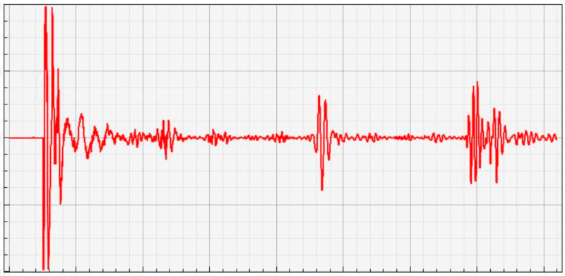
According to the schedule, several times a day, the DiLin system for some seconds enters the mode of electromagnetic parameters scanning using a test generator. During this period reflectograms are recorded.
The DiLin System Technical Specifications
To most effectively assess the overhead power line condition it is necessary to install two DiLin devices at the opposite ends of the power line.
It is possible to organize power line condition monitoring using one DiLin device installed on one side of the line. The disadvantage is that in this case the discharge activity location is impossible to realize.
The DiLin system is mounted at the place where the power transmission line enters the substation. It is installed in a IP65 mounting cabinet.
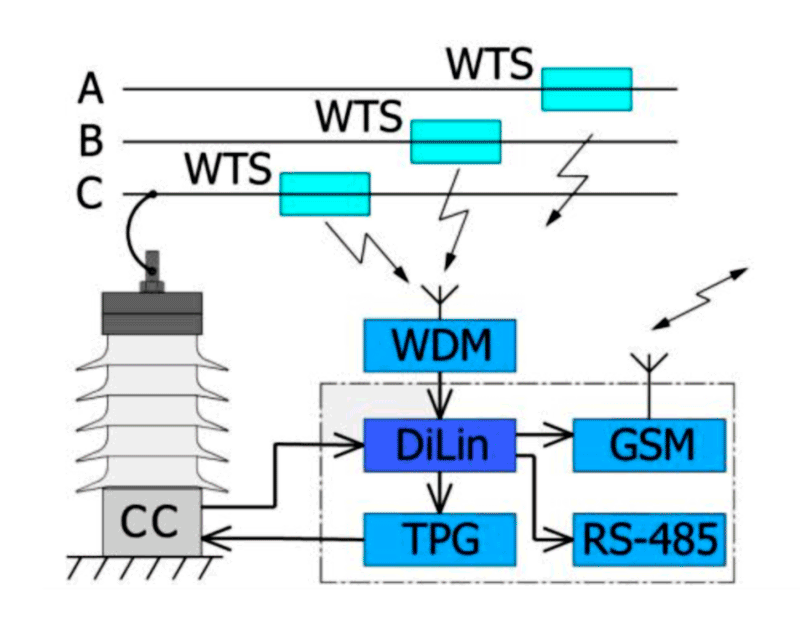
Coupling Capacitors (CC) are used as the primary sensors in the DiLin system. The number of coupling capacitors used corresponds to the number of power line wires monitored.
Using the managed switch (K) installed into the Dilin system cabinet, the built-in test pulse generator (TPG) connects in series to each phase wire of the power transmission line. In total, using one DiLin system, you can monitor 6 wires of the two power lines.
Using the managed switch (K) allows to record the average reflectograms for all wires of the transmission power lines under the operating voltage.
If there is an isolated lightning wire on the power transmission towers, which is most often subject to icing, the number of switched input channels in the DiLin system increases to 7.

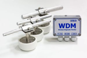
To monitor the wire temperature, wireless WTS temperature sensors are used. The WTS sensors are powered by the built-in battery designed for a service life of at least 20 years. The WTS sensors can also be powered by the power line wire current.
When using two Dilin devices at the opposite ends of the power line, it is necessary to synchronize the signals measuring with high accuracy.
This is done with the GPS/GLONASS system signals, the receivers installed in each device.
The complete set of the DiLin system includes PC workstation, which processes the information received from all the DiLin devices installed at the substation.
Information from all the DiLin devices is transmitted to the PC workstation computer via the interfaces available at the substation.
It could be:
- Optical or “copper” Ethernet line;
- RS-485 interface (TCP/IP protocol);
- GSM modem.
In the PC the integrated INVA Power Line software is installed, which is for overhead power line condition monitoring.
Using one PC workstation, you can monitor up to 12 power lines, that is, up to 24 DiLin devices can be connected to one PC workstation computer.

Diagnostics and Defect Location
The main method for overhead power line condition monitoring is the rapid detection of differences in the electromagnetic properties of the line in different parts of the line. This is done by injecting the test pulses into the line by test pulse generator (TPG).
For better noise rejection, several pulses are sequentially injected into the line, which allows them to be averaged by statistical methods.
The received reflectograms illustrate the monitored power line conditions. Any changes in the received reflectogram compared to the basic reflectogram mean the changes in the monitored power line condition. These changes may be associated with ice deposition, ground faults, insulation contamination, etc.
By using reflectograms, it is possible to determine the electromagnetic field wave velocity in the power line and the total attenuation of the test pulse. The place of the electromagnetic properties change in most cases is located with the accuracy “to the transmission line tower”.
If it is supposed to locate the places with increased discharge (thunder) activity, then it is necessary to install two sets of DiLin device: one at each end of the power line. In this case the place of increased discharge activity is determined by the difference in the pulse arrival to the two devices of the DiLin system.
Wireless temperature sensors (WTS) are mounted directly on the power line wires. The data from all the WTS sensors is transmitted to the DiLin system through the Bluetooth and WDM receiver connected to the system via a wired galvanically isolated RS-485 interface.
The DiLin device constantly monitors the ambient temperature. If it drops to +5 degrees and below, then the time intervals between the line scans are reduced, since the likelihood of ice formation increases significantly.
Device Installation at the Substation
The whole DiLin system, except coupling capacitors, is supplied in a protective metal cabinet designed for outdoor installation. This allows the system to be used in difficult weather conditions without taking additional measures to protect it from environmental influences.
If possible, the DiLin system cabinet should be installed next to the coupling capacitors. In this case, the signal cables from the sensors to the measuring device will be of minimal length.
The system includes a TPG-70 or TPG-200 test pulse generator built into the cabinet. The figure shows the maximum length of the line in kilometers for which this generator is designed.
Sending of test pulses from the generator to the line is also carried out using the same coupling capacitor, which serves to measure pulses reflected in the line.
The DiLin System Specifications
| Power line length, km | 5 ÷ 200 |
| Power line voltage, kV | above 6 |
| The number of the monitored power lines | up to 2 lines (6 phases) |
| Test pulse amplitude, V | up to 600 |
| Test pulse duration, us | up to 500 |
| Protective cabinet dimensions, mm | 500*700*250 |
| Supply voltage AC/DC, V | 120 ÷ 240 |
| Operation temperature, 0C | -50 ÷ +50 |


